Wednesday, 1 July 2015

Number Crunching

Today being a Wednesday, I don't go over to the Manor so it's a day catching up on administration or cracking on with a few computer odds and ends.

I tackled the creation of a data logger today. Call me old fashioned (well, I am Retrotecchie, after all) but I still like Visual Basic 6.0 for knocking up 'quick and dirty' Windows-based software for my needs. One of the advantages of VB is that most of the 'hobbyist market' PC interfacing kits or modules use standard DLL libraries which are easily accessed from VB with just a few lines of code.

The Velleman K8055/VM110 USB interface modules I have lying around not only have exactly the right I/O (both digital and analogue) but the DLL is exceedingly well documented. The modules also connect to a PC via USB which is nice for the laptop I use in the office as I don't have legacy Com or LPT ports and no way of adding a PCI or PCIe I/O card.

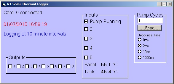
With this in mind, I knocked up a simple data logger today. On the basis that the program can run in the background all the time the laptop is running I decided that between 8am and 5pm when the solar thermal is 'active' a ten-minute logging interval would be fine. Outside those hours, I don't anticipate the system running much (or me being in the office) so I can extend the logging interval to twenty minutes.

The system reads the two temperature sensors on the differential thermostat and converts the voltages to direct Centigrade readout. The status of the pump (running or not) is also recorded.

The daily logging is output to a date-stamped text file, the contents of which can be imported into a LibreOffice Calc (or Microsoft Excel) spreadsheet and the data converted to a graphical representation. It also counts pump cycles so I can get an at a glance status of how many times the pump has run during the logging period.


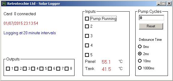
I can also toggle the digital outputs on the card just in case I want to use the card to control anything...lights, pump system or ancillary systems.

Although I developed this at home today, I've created a sample data file with 'faked' data just to see how it all works. The test board I'm using has a couple of potentiometers which I can manually tweak to simulate temperature readings and pump status. My 'faked' data looks a little like this:


This data can then be imported to a spreadsheet and converted to a graphical representation of system performance. This data can then be compared on a regular basis to see how it performs in different weather conditions or different seasons.


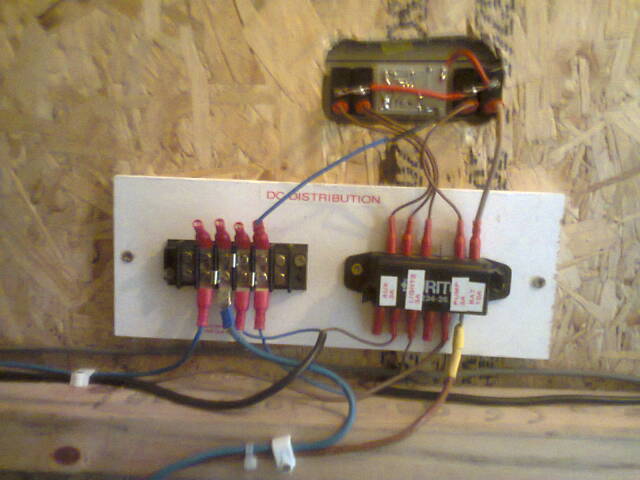
There's tidy. Some cosmetic refinements, and then a little work on the hardware to tidy the electronics up a little and I'm a happy bunny.


Tuesday, 30 June 2015

Recording Data

I've resurrected my old spreadsheet to log my grid and solar usage in the office now that I have both meters wired in and recording use and production.

Another thought crossed my mind last night. The two sensors used to trigger the differential thermostat to control the heating pump are nicely calibrated to provide 10mV per Kelvin, or degree Centigrade. At freezing point, they output 2.73v which represents 273K. 100 Centrigrade later, they give out 3.73v, so the entire range between 0 and 100 Centigrade is nicely within the limits of the pair of AtoD converters on my Velleman USB interface boards. So, by wiring in the interface to the sensor lines on the differential thermostat I can interrogate the voltage produced by each of the sensors, run a little simple maths and use the laptop to display the absolute and differential temperatures in degrees C.

Today around 1pm (the hottest day of the year thus far) and the sun just off the axis of the thermal panel, I recorded a temperature of about 68C on the panel and 64C on the return line from the calorifier.

What I need to do now is to create a data-logger that will allow me to record temperatures, and hence performance, over a longer period of time. A few days would be good...a few weeks even better, and graphical output would be very nice indeed. So, there's my next software project!

'twas bloomin hot today...not sure how hot but the van was hot. Hotter outside though. And, as I pulled out tonight, my min-max indoor/outdoor temperature/humidity gauge arrived in the post!


Turn Up For The Books

I posted a couple of days ago:

Two good output panels, one marginal and one very low indeed - probably faulty. Shelve that one for later fettling.

Well, I'd had the panels on the bench in the garage and at night, and the illumination was coming from a pair of fluorescent lights. Two panels measured 11 or so volts, one was registering about 9v and the 'faulty' panel was barely pushing a volt.

When I dragged the bad one outside into the sunshine today, output shot up to about 19v-21v off-load. Perhaps it's just not responding too well in low light levels. That said, the four panels I have would be of varying ages and amounts of use, so the measured values could be very different. A volt seemed a bit low when the other three were pushing out 9-11v in similar lighting levels. Ho hum.

Parallelled up, driving the charge controller, they'll be fine. All bought and paid for, over the years, so even if I do replace them later on down the line, they don't owe me anything. If I can screw 30Wp out of the four, I'll be happy enough.


Sunday, 28 June 2015

Two Steps Forward, One Step Back

Progress today:

Second solar panel installed - doubled up on battery input.


Camping Gaz cooker in place.


AC side of the inverter system in place and wired in. All working, apart from one niggling problem that needs investigating. I think I may need to review my schematic as there is something very odd going on and all the staring at the wiring isn't helping me any :o(

This may have a bearing on matters. For the first time I have combined a grid-fallback system with an inverter hold-on/LVD system. I'm wondering if this is causing my problem?

Friday, 26 June 2015

Salad Harvest

Remember my pallet-wood salad planter?

Our first harvest!


Thursday, 25 June 2015

And Ever Closer


Along with the volts (in red) we can now see the amps (in blue). A cloudy and overcast start to the afternoon today, so the single panel was only charging at around 150mA but the voltage is where it should be. 


The inverter has been dug out of the storage box and is screwed into position in the facilities. DC side all wired up to the battery via the Low Voltage Disconnect relay. The relay hold-on supply was taken directly from the inverter output for testing. I still have the AC side of things (including the kWh meter) to wire up, but there is 300W of pure sine mains to be had for the asking.


With the inverter operating, the battery voltage has dipped just a shade and you can see a net draw from the battery of 0.68A. The power load is thus about 8.2 watts (A x V), of which 3W or so is for the hold-on relay and the rest is the standby consumption of the inverter itself. 


The kitchen worktop extended along the side wall. Space here for my Camping Gaz cooker.

I got lucky today. I ran an ethernet CAT5 cable down from the Manor in the hope of getting some internet connectivity. Maximum length for a point to point link is about 100m. The cable measured in at 96m more by luck than anything else. I also installed the table I made from the offcut of my workbench.


With the ethernet in place and the table looking good, I cranked up the laptop to check on emails. 

Today I also spent a bit of time scraping some of the cack off the walls so they are starting to look a little better now. The office is almost useable now! The 12v light in the office has had the cable trunked and with clean(er) walls, it looks almost acceptable now.

Wednesday, 24 June 2015

Solar PV Progress


One panel connected to the Maplin charge controller (recycled from the old 60W Solar kit). Not the best controller in the world, but for testing purposes it does have an LED voltmeter which does save faffing with my DMM every time I want to test anything. It was a bright day, although the sun was well over to the west when I took the photo so the panel was just getting diffuse light, but that's fine for a thin film panel. Battery showing a healthy 12.7v under load.


Unlike previous tinkering, this time I have a proper DC distribution panel. All the outputs from the Zig SP-4 are fused (3A per circuit) and the main battery incomer (bottom right) 4mm cable is fed to the Zig via a 10A fuse. 120W for all the supplementary DC systems should be plenty. The inverter system will run directly from the battery bank via it's own dedicated high current fuse. The black 0.5mm twin mains cables feed out to two separate lighting circuits. One is the 12v strip-light shown in a previous post, the second circuit feeds a second strip-light out in the main office area as well as the LED pelmet lighting in the kitchen.

I still haven't bothered with a secondary battery...I can always add one later if necessary - it might be needed in winter. I have a spare way on the fuseholder and plenty of spare capacity on the negative commoning strip. On the other hand, I can also see the possibility of wiring in an external DC socket to this secondary battery circuit. In a dire emergency (100% cloud on a winter's day, no charge and a flat battery and the mains off-line) I can hook up an Anderson cable to any of the vehicles (including Squeaky Joe in a pinch!) and have emergency 12v power.


Temporary fixing of the office strip-light. I need to clean the walls and decide on a finish before I fit anything permanently.


The kitchen LED lighting is very funky. I'm debating running a 12v feed to the fridge. The Peltier heat-pump and fan consume 48-60W (4-5A) from a 12v DC supply, but consumption is about 70W on the mains power pack. I'm guessing that some power is lost in conversion. I'm going to keep both options open. What I'm not going to do is use an inverter (12v < 240v) to drive a mains adaptor (240v > 12v) to power the fridge...that really would be inefficient! If I go for a DC supply, I'm going to pulse control it (on-off-on-off) so it doesn't run continuously 24/7. To be honest, at night it barely needs to be on at all once it is down to temperature.


And the 'bargain' £4.99 cabinet doors I bought in Craft hoping they would fit the kitchen cabinets? They didn't, but some pallet-wood to make a carcass and a couple of offcuts of scrap OSB...my 'brew centre'! I have my tea, coffee, sugar and Cup-a-Soup stashed in here, with the mugs on hooks underneath. Hey, I'll recycle anything, I will.

Grrr....I still haven't got a picture of the return on my worktop. Perhaps tomorrow, once I've installed the cooker. 

Yes, you read that right. A cooker.