Thursday, 25 June 2015

And Ever Closer


Along with the volts (in red) we can now see the amps (in blue). A cloudy and overcast start to the afternoon today, so the single panel was only charging at around 150mA but the voltage is where it should be. 


The inverter has been dug out of the storage box and is screwed into position in the facilities. DC side all wired up to the battery via the Low Voltage Disconnect relay. The relay hold-on supply was taken directly from the inverter output for testing. I still have the AC side of things (including the kWh meter) to wire up, but there is 300W of pure sine mains to be had for the asking.


With the inverter operating, the battery voltage has dipped just a shade and you can see a net draw from the battery of 0.68A. The power load is thus about 8.2 watts (A x V), of which 3W or so is for the hold-on relay and the rest is the standby consumption of the inverter itself. 


The kitchen worktop extended along the side wall. Space here for my Camping Gaz cooker.

I got lucky today. I ran an ethernet CAT5 cable down from the Manor in the hope of getting some internet connectivity. Maximum length for a point to point link is about 100m. The cable measured in at 96m more by luck than anything else. I also installed the table I made from the offcut of my workbench.


With the ethernet in place and the table looking good, I cranked up the laptop to check on emails. 

Today I also spent a bit of time scraping some of the cack off the walls so they are starting to look a little better now. The office is almost useable now! The 12v light in the office has had the cable trunked and with clean(er) walls, it looks almost acceptable now.

Wednesday, 24 June 2015

Solar PV Progress


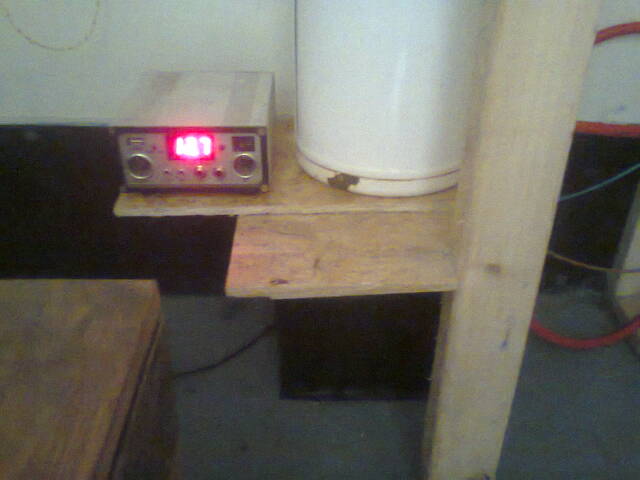
One panel connected to the Maplin charge controller (recycled from the old 60W Solar kit). Not the best controller in the world, but for testing purposes it does have an LED voltmeter which does save faffing with my DMM every time I want to test anything. It was a bright day, although the sun was well over to the west when I took the photo so the panel was just getting diffuse light, but that's fine for a thin film panel. Battery showing a healthy 12.7v under load.


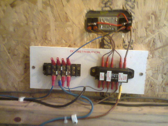
Unlike previous tinkering, this time I have a proper DC distribution panel. All the outputs from the Zig SP-4 are fused (3A per circuit) and the main battery incomer (bottom right) 4mm cable is fed to the Zig via a 10A fuse. 120W for all the supplementary DC systems should be plenty. The inverter system will run directly from the battery bank via it's own dedicated high current fuse. The black 0.5mm twin mains cables feed out to two separate lighting circuits. One is the 12v strip-light shown in a previous post, the second circuit feeds a second strip-light out in the main office area as well as the LED pelmet lighting in the kitchen.

I still haven't bothered with a secondary battery...I can always add one later if necessary - it might be needed in winter. I have a spare way on the fuseholder and plenty of spare capacity on the negative commoning strip. On the other hand, I can also see the possibility of wiring in an external DC socket to this secondary battery circuit. In a dire emergency (100% cloud on a winter's day, no charge and a flat battery and the mains off-line) I can hook up an Anderson cable to any of the vehicles (including Squeaky Joe in a pinch!) and have emergency 12v power.


Temporary fixing of the office strip-light. I need to clean the walls and decide on a finish before I fit anything permanently.


The kitchen LED lighting is very funky. I'm debating running a 12v feed to the fridge. The Peltier heat-pump and fan consume 48-60W (4-5A) from a 12v DC supply, but consumption is about 70W on the mains power pack. I'm guessing that some power is lost in conversion. I'm going to keep both options open. What I'm not going to do is use an inverter (12v < 240v) to drive a mains adaptor (240v > 12v) to power the fridge...that really would be inefficient! If I go for a DC supply, I'm going to pulse control it (on-off-on-off) so it doesn't run continuously 24/7. To be honest, at night it barely needs to be on at all once it is down to temperature.


And the 'bargain' £4.99 cabinet doors I bought in Craft hoping they would fit the kitchen cabinets? They didn't, but some pallet-wood to make a carcass and a couple of offcuts of scrap OSB...my 'brew centre'! I have my tea, coffee, sugar and Cup-a-Soup stashed in here, with the mugs on hooks underneath. Hey, I'll recycle anything, I will.

Grrr....I still haven't got a picture of the return on my worktop. Perhaps tomorrow, once I've installed the cooker. 

Yes, you read that right. A cooker.

Sunday, 21 June 2015

Solar Phase 2

The 12v DC system is underway. Solar PV, in other words. Yesterday evening I dug out a set of Topray 12W TF panels, ex my old shed, which have been sat in storage for a year. Two good output panels, one marginal and one very low indeed - probably faulty. Shelve that one for later fettling.

I took one good panel over today and temporarily mounted it above the solar thermal collector.


This position is not optimal, but gets solar input for the same early morning period as the thermal panel. 


The panel is connected via the Maplin charge controller to a battery in the plant room. The output from the battery is wired into a Zig SP-4 switch panel recovered from a scrap caravan. This piece of kit has a 1991 date-stamp on it, so it's pretty vintage, but as it is a simple switch panel with just a good/bad LED battery condition indicator, there's not too much to go wrong with it. The left hand switch allows selection of caravan or car battery. In this setup, I'm going to have two selectable on-board batteries so I can switch from one to the other when the charge state gets low. The pump switch would normally operate a Whale pump in a wheelable water barrel for caravan use, but here it is used to power the electronic differential thermostat for the solar water heating. The Lights switch function carries over directly, and is used to switch DC lights on and off. The Aux is spare for now but I may use it as an inverter control switch for off-grid AC mains.


I also salvaged a pair of 18W tubular fluorescent 12v lights from the caravan, so I am using these as my backup 12v lighting system. One of these is mounted in the kitchen, shown above, and the other will be installed in the office area. The 12v lighting circuit will also power my LED pelmet light in the kitchen and reading lights in the office area.


The above picture shows the kitchen light and the Zig control panel.


The kitchen has now been cleared up a little and is pretty much up and running for brewing up and hot hand wash. Unfortunately I ran out of coffee granules today so had to resort to a few random teabags I had sculling about....ewwww.


And with the floor swept and a doormat installed, we are looking almost like a finished item now. Just the final cladding on the front wall, trimming round the ceiling and some cladding in the loo, and we have an office almost ready to start kitting out.

Wednesday, 17 June 2015

Plumbing Technical Detail

I have been asked to show a bit more of the technical aspects of the van plumbing by a fellow DIY'er to show clearly how the system works. Here is the master plumbing diagram:


As a step by step guide, here's how it works.

Rainfall is collected by the gutter running around the perimeter of the roof. This rainwater is fed into an open cell Polyethelene Foam protected slow sand filter. This provides biological filtering as well as sediment and particulate filtering to the raw rainwater. What comes out of this filter is 'clearwater' which is then stored in a 120 litre plastic tank. This tank has an overflow pipe (not shown) to allow excess water to run out of the system. After the storage tank, the water is split two ways. One path flows through the IX600 reverse osmosis and carbon filter rendering the water almost 100 pure and pretty much potable. This cold supply is fed to the cold tap in the kitchen and is used to provide the drinking water for coffee, etc. The flow rate isn't great as the IX 600 filter is fairly restrictive off mains pressure (I only have about 0.9m of static head at best), but it is more than enough for potable purposes.

The second path from the storage tank is used to fill the calorifier cylinder at the lower end. This calorifier is an electric undersink 5 litre water heater that has had the immersion heater element removed and a heat exchanger copper coil fitted. The hot water generated by the solar collector is pumped through this coil, allowing the water stored in the 5 litre stainless steel tank to take up the heat produced. Hot water then exits the top of the calorifier when the hot tap is used in the kitchenette. The flow is better than the cold as it has no restrictive filtering inline.

Unlike a conventional domestic HW system, the header tank for the solar is not fed from a mains supply to allow for evaporation or seepage in the system. With a maximum primary circuit volume of around 6 litres, an automatic top-up of the solar circuit was not deemed necessary. Likewise, a separate feed and expansion (with vent pipe) was not required as any air is purged from the system when it is first filled and the excess water in the header tank is purely to allow the total volume of the water in the primary circuit to increase or decrease as a function of temperature.

For simplicity, I have also omitted such items as the Y-strainer and isolator valve in the flow from the panel, draindown valve at the lowest point in the system and the isolators for the hot and cold water systems.

Tuesday, 16 June 2015

The Heat Is (Finally) On!

Tada! We have solar thermal, and it's good stuff! I have to say my previous dabblings with solar thermal were fun, instructive and successful as far as they went, but this system really shone today, as did the sun.

A few delays this morning garnering supplies meant I didn't get into gear until just after 11am so I figured I only had a short window of opportunity for making the most of the sun round the back of the van.

Well...


Hot supply to sink tap connected up.


Cold feed to calorifier hooked up. I opted for a hose connection plus an isolator valve at each end just in case I needed to remove anything in future.


Feed and expansion (header tank) all plumbed in and topped up with 6 litres of water. Pump conversion in and doing, thermal sensors coupled to panel and return pipe and electrics all in and working.


Pump supply wired in to plant-room spur and controlled by the differential thermostat. The green light shows power is on and the red light indicates that the pump is running.


Ok, so you can't really tell from a photo, but the water coming out of the tap at around 2pm was gorgeously hot...almost to the point where I was seriously thinking about having to install a tempering valve in case it got too hot. At 4pm this afternoon, with the sun away from the panel, there was still enough diffuse heat and light for the system to be generating useful heat.

I also trimmed the return on the worktop, tidied up the kitchenette a little and swept the floor for even more feelgood factor.

So thus far a toilet/plant room with composting loo, solar hot water and a rainwater filtration and harvesting system, a kitchenette with hot and cold running water, electrics and storage and an 11ft office space with lights, power and a sound system. Just the solar PV to install now, a network and phone hookup, the final finishing and fitting out and Retrotecchie's new 'office' is ready to rock!


Monday, 15 June 2015

Boll%@!s

All was going so well, and then I broke the Topsflo solar circulator! Nothing to be done about it, but come up with a plan B for the time being. I tried to repair it, but an 8mm copper tube insert and a podge of silicon rubber wasn't going to do it. Leaking like a sieve, no flow through the calorifier and game over for the day. Which was a shame...the solar collector, once filled with water, was getting hot enough to burn my hand on it.

A quick Google, and I can find a replacement pump, but not much change from £60 and about 2 weeks to ship one in from the USA. In the mean time...no hot water.

But...hiding in the polytunnel I have the Wilo Gold circulator which was my first pump I'd used on my wood-fired system. Mains powered, and consuming 35W on it's slowest speed, I'd replaced it with the Topsflo as that only needed 15W at 12vDC and could be battery-powered off grid. As we have power to the shed, this isn't so much of a problem now. Yes, a power overhead but not a complete stumbling block. I removed my short lengths of 15mm copper in the pump line (so I can refit a replacement Topsflo if and when I can find one) and began to fettle the suitable pipework to take the 22mm pump flanges. I ran shy on materials so I need to get a few bits in the morning.

On the upside, I have modified the Maplin Temperature Controlled Switch kit to work as a differential controller using a pair of LM335Z sensors as my inputs. In order to drive a mains-powered pump, I've added a 2A round pin socket (with the plug on the pump cable) and fitted a higher-powered relay. All seems to work just fine and bench tests show excellent results.

So, the collector works, the calorifier is a known quantity, and all I need to do is hook up the pump and get it running. The secondary circuit (cold supply to the tank and hot out to the tap) should be reasonably straightforward. I could have done without the hassle, but as it turned out, the 3m length of tube I'd bought on Friday wasn't enough anyhow, so no major hassle. I'll just be a few days behind on my hot water plans, but that's not the end of the world.

One minor consolation....the Wilo pump I bought on ebay about 4 years ago, for something like £40, now costs about £200 new! If nothing else, I've reused and recycled an expensive surplus item.

Thursday, 11 June 2015

Another Step Closer

The solar hot water is a step closer today. I toddled over to the box today via Jewson's in the hope of picking up the balance of materials I needed for the primary circuit. The secondary is just a matter of hooking up the cold inlet and a feed pipe to the hot tap, so that's not a really big job, but the primary is a little more involved and I really wanted to get that finished and tested if I could.

Well, Jewsons are handy, but their prices for compression fittings almost made me choke and I didn't even bother to ask what their copper tube prices were! By all accounts, B&Q are actually cheaper, plus I now have Tradepoint so I get their products at a significant discount. I'll pick up what I need tomorrow and finish the plumbing on Sunday. Instead of working on the plumbing side of things, I had a session on the panel itself.

I needed to glaze the panel. This keeps in solar heat that would otherwise radiate straight back off the collector - rather like a greenhouse, the solar energy gets in but has a hard time getting back out again. Eco had a couple of old sealed double glazing units behind a shed. He asked me a while ago if we had any use for them and I'd mentioned using them to glaze a solar collector.

Sometimes in life you get just a bit lucky. Ideally, I needed a piece of glass 60" by 25" and there was one unit that caught my eye in particular. When I ran a ruler over it, it turned out to be 52" x 25". Not perfect - a spot on 60" would have made me very happy, but I figured 52" would do to be going on with.

First job was to take a Stanley knife to the sealed unit and remove the aluminium foil from around the edge of the unit and cut through the mastic to try and separate the two panes of glass. Double-glazing sounds like a good idea for a solar collector - if one pane of glass keeps the heat in, surely two is better? Not so, apparently. It seems that two sheets of glass with an air-gap in between not only reduces the heat energy impinging on the collector but doesn't work as effectively as a greenhouse. 


The missing 8" of glass cover has been overcome with two strips of wood 4" wide, one at each end. The collector's effective area has been slightly reduced, but I gain the advantage that the glass can be sealed to the frame in a permanent manner, but the ends of the radiator can still be accessed just in case I need to get to the compression fittings for maintenance purposes. All things considered, I think that works a little better.


On the return side of the panel, I have fitted a tee and an appliance valve. This will allow me to drain down the system if necessary, for maintenance or if extremely cold weather is expected in winter. The system will be protected by antifreeze, but you can't be too careful in a Welsh winter. Rather than take the return pipe through the wall of the van at this end, it folds back under the panel so both the flow and return enter inside the 'plant room'. This means the main internal wall of the body is free of pipework.


On the flow side, or outlet, I have fitted a Y strainer. Whereas this is possibly not essential, it does include an isolating valve. I'm not sure how bad the inside of the radiator is, but I have to assume there will be some scale, rust and debris in there. The strainer will allow me to sieve out any grollies before the pump while I am commissioning the system. I expect the first couple of hours of testing will entail several draindowns and refills to get the worst of the detritus out of the system. The pump itself will tolerate some degree of contamination, but I also have a very tight bend in the immersion primary in the calorifier so I want to try not to let that get blocked.


The total capacity of the system's primary circuit is about 5 litres, so I have used an 18 litre plastic lidded box as my feed and expansion tank. This doesn't have a water supply so filling and topping up will be done manually as part of my daily checks. I now need to find another box...the one I had immediately to hand was my tea-boat! Just in case of overenthusiastic filling, it does sport an overflow, but this is hopefully just for testing and will be removed and blanked off once up and running. The hole in the back of the wall letting the sun in is the hole where the return pipe will leave the van. You can just make out a foot of pipe missing between the tee piece and the pump inlet. The arm of the tee is the vertical feed pipe from the F&E tank. I may need a vent pipe in there too, like a standard vented CH system. Experimentation will determine if this is needed not.


Here you can see my modified OSO undersink water heater I am using as my calorifier/heat exchanger. The immersion has been replaced with a couple of loops of microbore pipe, one for solar and one for an alternate heat source. In the old Tool Shed, this loop was fed from my incinerator loop. The pump is my Topsflo Solar circulator, again repurposed from the old shed. Just behind this on the wall is my pump controller. It is simply a temperature sensor on a flying lead which generates a small voltage on one input of a comparator chip. This is compared againt a 'set point' which can be adjusted, therefore acting as a simple DC thermostat driving the pump relay. In the past, as soon as enough heat was generated in the incinerator, the flow pipe got hot and the sensor picked up this heat and turned the pump on. When the water started to flow, the pipe cooled down enough to switch off the pump and then the heat would build up again and the system would cycle. 

I have the option to modify the system to work as a differential controller and use two sensors. One will monitor the panel output and the other will monitor the calorifier. If there is more heat in the panel than in my water tank, the pump will run. As soon as equilibrium is achieved, the pump will stop. This ensures that the system will only pump when there is a net energy gain to be had. Whether I need to go to a differential system, I shall find out once the system is tested.